Prüfung und Wartung
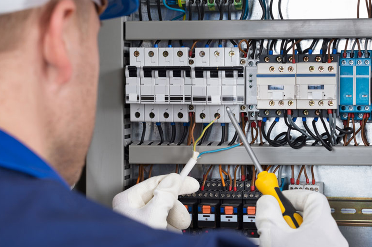
Know-how und Erfahrung aus der Beteiligung am Bau zahlreicher Gewerbe- und Industrieanlagen zeichnen uns als zuverlässigen Partner im Bereich Wartung, Prüfung und Messung aus.

Dabei wenden wir die optimalen Methoden auf modernsten Mess- und Prüfeinrichtungen an, um erfolgreich auf die Anforderungen unserer Kunden einzugehen, sei es bei der Prüfung von Kraftwerken, Leitungen, Anlagen oder der Stromqualität , sowie das Testen von optischen und strukturellen Kabelnetzen. Hochqualifizierte Expertenteams unseres Unternehmens machen Ihre Kraftwerke und Anlagen für alle Ihre Geschäfts- und Produktionsvorhaben sicher, effizient und zuverlässig.
Regular maintenance includes the preventive maintenance process of all distribution plants and would last for about six months.
Inspection is performed twice a year at all mentioned locations and includes the following steps:
1. Visual inspection of cabinets and preventive maintenance
• Includes a detailed inspection of all the built-in elements in the cabinet;
• Control and inspection of distribution cabinet equipment (couplings: bus bars: ground and zero, clamps, fuses, switches, contactors, assisting contactors, relays …);
• Control and inspection of the AS switch to check the parameter settings as well as the disconnection test;br> • Keeping a book about an individual cabinet maintenance;
• Life expecting control of the built-in elements and replacing them when needed;
• Entry of the changes in the design documentation;
• Preventive maintenance planning.
2. Thermographic inspection of the cabinets
• Includes ispection of the cabinets with a thermal imaging camera;
• Reports with digital images
3. Emergency maintenance
• Includes responding to an emergency call by the client
– In case of emergency interventions where delay may cause damage, the response of the specialized team is immediate – no more than 120 minutes..
– In cases of less urgent interventions the response of a specialized team is within 24 hours.
Phase I: Measuring of the quality of electrical energy:
• Statistics on the voltage quality analysis in accordance with the regulations of EN 50160
• Measuring of voltage operations (interruptions, increase, reductions);
• Continuous recording (during measuring) of the following:
– Voltages (minimum, maximum, medium);
– Electricity (maximum, minimum and mean);
– Power (S, P, Q) maximum, minimum and mean values;
– Power factor COS;
– Flickers;
– Asymmetry (asymmetric load);
– Frequency;
– Measuring of higher harmonics in the grid (up to 50th).
Phase II: Thermal imaging of distribution cabinets:
Infrared scanning (thermography) allows you to get a good insight into the state of the electrical installation without having to turn it off or even touch the components. Thermography offers a method of detecting energy losses and upcoming errors due to overheating, poor or loose contacts, etc. In addition to avoiding unplanned shutdowns and production losses thermography can help to assess the energy use. The costs of regularly performed thermography are small compared to the benefits.
Purpose of thermography is multiple:
• Increase the safety of electrical installations by checking the state of the various components of electrical installations (installations, connections, switches, transformers, motors, etc.);
• Unbalanced load and insufficient thickness of conductors;
• To reduce slowdowns and avoid unplanned shutdowns thermography detects failures before breakdowns. A routine thermal imaging inspection can detect potential malfunctions on electrical components.
Typical electrical problems:
• Loose connection;
• Poor connection (poorly installed, corroded connection, deterioration due to mechanical malfunctions, etc.);
• Unbalanced load;
• Invalid equipment;
• Too small conductors;
• Overheating of the engine;
• Overloaded conductors;
• Potential fire risks;
• Accelerated component wear;
• Harmonics problems.
Electrical current generates all the heat in electrical installations. More than 40% of the energy consumed by the industry is electrical which means that the optimization of electrical installations and correcting errors is very useful.
A recent study showed that the average electrical losses in the industry amount to 2% of the total electrical energy consumption. Losses due to poor contacts represent one-third and make 40% of savings after corrective actions have been taken. (Source: US Department of Energy). One study showed that poor contact of 0.5 ohms increased to 1 ohm after a week and up to 10 ohms after a year.
• It enables smooth operations of the facility.
• Places where fire or breakdown may occur can be located on time.
• Maintenance costs are reduced.
• Losses due to delays / interruptions are reduced.
• It is possible to create a unique and efficient plan for scheduled maintenance.
• Recording the actual state in technical processes and reactions.

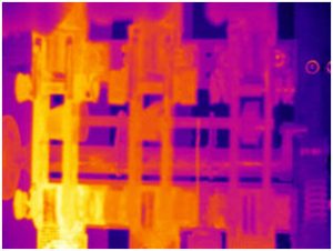
By thermography, we timely discovered overheating of one of the contacts on the switch in the substation:

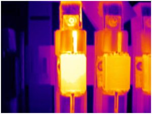
Or poor contact at the fuse

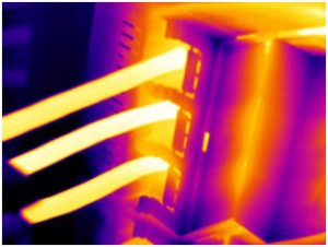
Or conductors overload
